DCN Quiz 2 · Engineering diagrams & worked explanations
Layers inside a network
A layer is a set of jobs inside a device. A protocol is the rule set used to do one of those jobs. Start with the whole stack, then follow one packet.
You do not need five separate machines for five layers. Your laptop runs all five. A normal switch forwards at Layer 2; a normal router forwards at Layer 3.
The same transmission, five responsibilities
Read down the table on the sending host. Read up on the receiving host. The layers cooperate; they are not five competing ways to send a message.
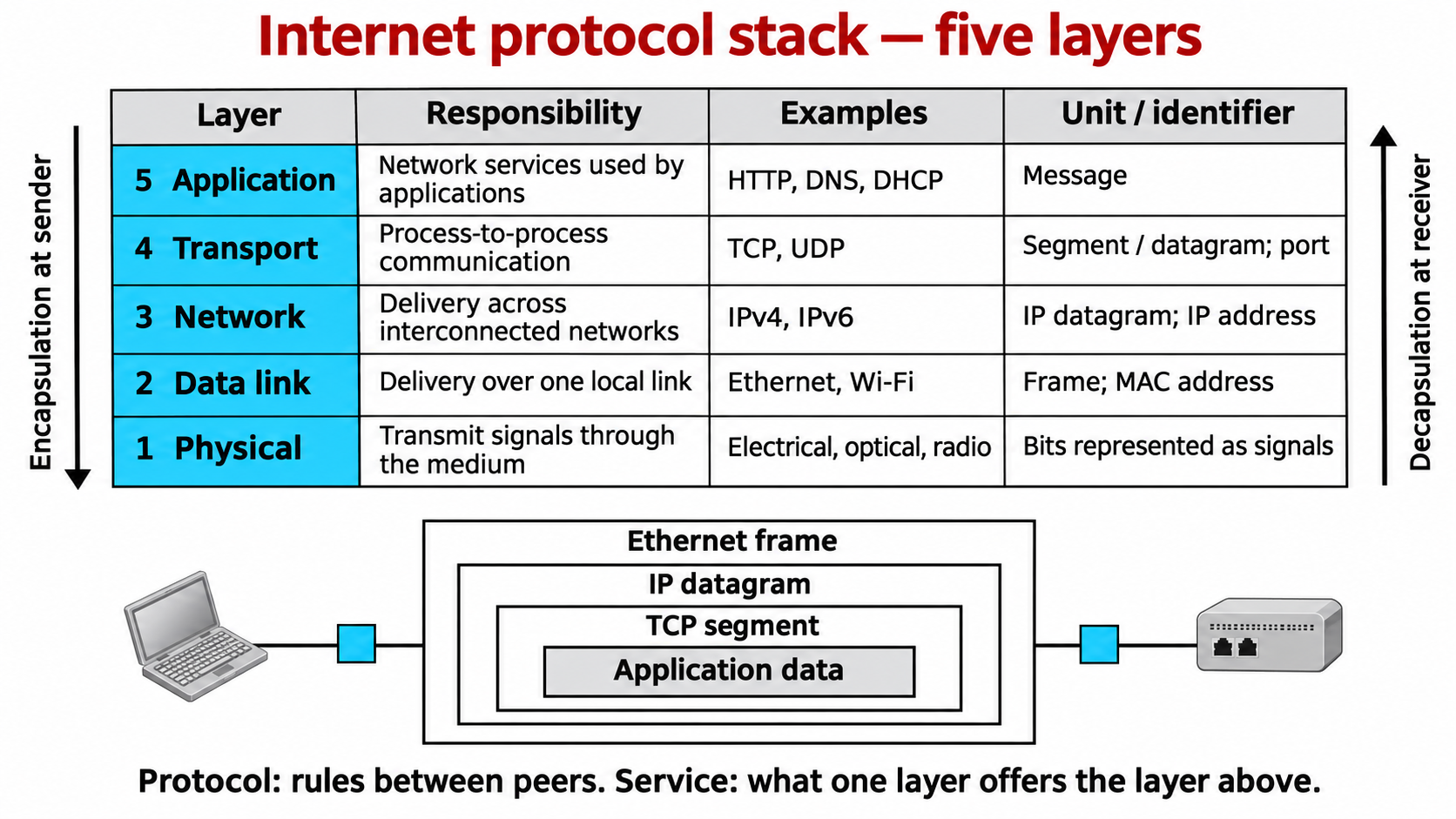
Select a layer to see its job
Use the “Related definitions” links beneath the selected layer to open a plain-language definition.
What talks to what?
Layer
A responsibility group. The network layer handles delivery across networks. It is a conceptual part of a device’s networking software/hardware, not a separate cable box.
Definition: layerProtocol
Rules between peers. TCP at the sender and TCP at the receiver agree on TCP fields and behavior. HTTP peers agree on requests and responses.
Definition: protocolService / interface
What the adjacent layer can use. An application asks transport to send data. Transport asks IP to carry its segment. Each layer uses the one below it.
Definition: serviceUse two views at once. Vertically, each layer provides a service to the adjacent layer above it: HTTP hands a message to TCP, TCP hands a segment to IP, IP asks the link layer for one-hop delivery, and the physical layer carries the frame's bits. Horizontally, matching protocols at the two end hosts behave like logical peers—for example, the client and server applications follow HTTP rules—but the real data travels down one host's stack, across the network, and up the other host's stack. Routers normally act on IP and rebuild link frames; switches normally act on MAC-addressed frames; neither needs to read this HTTP request. The packet journey below uses plain, unencrypted HTTP over TCP solely as a teaching example; it does not imply that all web traffic uses this protocol/port combination.
| At the receiver | What identifies the next protocol / recipient? | Example |
|---|---|---|
| Data link → Network | Ethernet EtherType identifies its payload protocol. | 0x0800 = IPv4; 0x86DD = IPv6; 0x0806 = ARP. |
| Network → next protocol | IPv4 Protocol (IPv6 Next Header) identifies what follows. | 6 = TCP; 17 = UDP; 1 = ICMP in IPv4. |
| Transport → process endpoint | Port numbers help direct data to the intended socket / application. | TCP destination port 80 in this HTTP teaching example. |
These fields are identifiers at different boundaries. An IP address is not a port number; a TCP port is not a switch’s physical connector.
Where do ARP, ICMP, DNS and DHCP fit?
ARP: resolves a local next-hop IPv4 address to a MAC address. It crosses the network/link boundary and travels directly in a link frame, not inside TCP/UDP or an IPv4 datagram. ICMP: a network-layer control/error protocol carried inside IP. DNS and DHCP: application-layer protocols, even though their work helps configure or locate network-layer addresses. DNS can use UDP or TCP; DHCP uses UDP in the classroom exchange.
Do not force every protocol onto one vertical pipeline. HTTP→TCP→IP→Ethernet is one flow. ARP is a separate local exchange needed before the data frame can be sent when the MAC mapping is unknown.
HTTPS adds TLS for the common HTTP/1.1 or HTTP/2 over TCP case. HTTP/3 uses QUIC over UDP; “all web traffic uses TCP” is too broad. You can focus on the explicit HTTP-over-TCP example here to understand layering.
Watch the headers get added and removed
The payload is relative to the layer you are looking at: a complete TCP segment is the payload of an IP datagram. The link frame then carries that complete IP datagram.
This is a conceptual containment diagram. It is not a byte-accurate header layout. The physical layer encodes bits as signals; it does not add another “physical header” around the frame.
Which layers does each device use?
Both end hosts use all five layers. Ordinary forwarding inside a switch uses the bottom two; ordinary IP forwarding inside a router uses the bottom three.
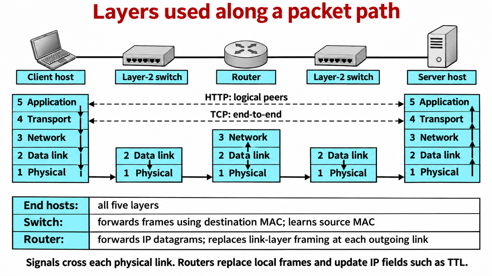
Trace one request across two LANs
Client 10.0.1.10:51514 sends to server 10.0.2.20:80. Router interfaces are 10.0.1.1 and 10.0.2.1. We use two switched Ethernet LANs, plain HTTP over TCP, no NAT, and symbolic MAC names A, R1, R2, B.
On a phone, swipe across this engineering diagram. The step controls below explain it in reading order.
Destination IP
Stays 10.0.2.20 through the normal routed path. The router is the next hop, not the final destination. Other IP fields, including TTL and IPv4 header checksum, change.
Destination MAC
First LAN: R1, the gateway’s local interface. Second LAN: B, the server’s NIC. The router replaces the frame; the switches do not rewrite its MAC pair.
Destination TCP port
Stays 80 for this request. It identifies the server endpoint used in the example. Normal IP forwarding does not need to deliver the segment to a web application in the router.
Repeater, hub, switch, router: what decision can it make?
| Device | Uses layers | Ordinary action | Cannot infer from its normal role |
|---|---|---|---|
| Repeater / hub | Physical (1) | Regenerates/retimes signals; a hub repeats them to other ports. | Which destination MAC or IP should receive the data. |
| Layer-2 switch | Data link + Physical (2,1) | Learns source MAC → incoming port; looks up destination MAC to forward or filter. | An end-to-end IP route from its Layer-2 forwarding table. |
| Router | Network + Data link + Physical (3,2,1) | Reads destination IP, selects next hop/output, updates TTL, creates outgoing frame. | The application’s message meaning from basic IP forwarding alone. |
| End host | All five | Creates or consumes application messages using the whole stack. | That every packet it sees is meant for its application. |
Why do some diagrams show seven layers?
They are using the OSI reference model, a different way to group responsibilities. The five-layer Internet teaching model separates physical from data link. Four-layer TCP/IP diagrams combine those bottom two as “link” or “network access.” These are different maps of related jobs, not a demand for seven separate machines.
| OSI layer | Responsibility | Five-layer Internet grouping |
|---|---|---|
| 7 Application | Network services and application protocols used by programs. | Application |
| 6 Presentation | Data representation, encoding, or transformations when required. | No separate layer; these functions are generally handled by application protocols or libraries. |
| 5 Session | Dialog/session coordination when required. | No separate layer; these functions are generally handled by application protocols or libraries. |
| 4 Transport | Process-to-process delivery and transport services. | Transport |
| 3 Network | Host-to-host packet delivery across networks. | Network (Internet layer) |
| 2 Data Link | Frame delivery over one link. | Link |
| 1 Physical | Signals carrying bits over a medium. | Physical |
In the Internet model, application protocols/libraries handle the functions associated with OSI application, presentation and session. For example, encoding, security and conversation management may be handled by application code or supporting libraries. This mapping is conceptual; calling TLS “always exactly OSI layer 6” is an oversimplification.
Understanding checks: explain the reason
Look away from the diagram and give a two-sentence answer before revealing the explanation. Include what the device or protocol knows, and why that information is enough.
When the browser and web server exchange an HTTP message, does it travel directly between the application layers?
That is a logical peer-to-peer relationship: each application follows HTTP's message rules. In the actual transmission, the request passes down the client stack, crosses links and routers, then moves up the server stack.
Why: Keeping logical peer communication separate from actual adjacent-layer delivery explains why a router forwards an IP datagram rather than handing an HTTP message to a browser process.
What does one layer receive from the layer below it?
It receives the service of the adjacent lower layer. For example, IP asks the link layer to carry its datagram to the next node on the current link.
Why: Layering works because each layer uses a lower layer's service and provides a more useful service to the layer above.
What is the difference between port 80 and IP address 10.0.2.20?
10.0.2.20 identifies the destination host/interface at the network layer. TCP destination port 80 identifies the server-side transport endpoint on that host.
Why: A packet needs both a network destination and a destination application endpoint; one number cannot replace the other.
Why does the MAC pair change at a router while the IP pair stays fixed in this example?
The Ethernet frame delivers the IP datagram over one local link. The router removes that frame and builds a new frame for the next link, using the next-hop MAC addresses. Without NAT, the datagram's source and destination IP addresses remain 10.0.1.10 and 10.0.2.20; TTL is decremented.
Why: IP describes the end-to-end endpoints, while MAC addresses deliver a frame across a single link.
The server is outside 10.0.1.10's local subnet. Which IP address does the client resolve with ARP before its first frame?
It resolves its default gateway, 10.0.1.1, to a MAC address on the source LAN. The IP destination in the datagram remains the server, 10.0.2.20.
Why: A host sends an off-subnet IP datagram to its next hop; ARP resolves the local next hop, not a remote server's MAC address.
Is ARP a TCP header or the payload of this HTTP request?
No. ARP is a separate protocol used to resolve an IPv4 address to a link-layer address on the local network. It is not nested inside the TCP segment carrying HTTP.
Why: The host may need ARP before it can form an Ethernet frame, but that support exchange is distinct from application data encapsulation.
Which addresses does a normal Ethernet switch use to forward a frame?
It learns from the source MAC address and looks up the destination MAC address to choose an output port.
Why: A link-layer switch works with frames and MAC addresses; it does not normally choose a route by inspecting the IP destination.
Does the LAN switch rewrite A's source MAC or the gateway's destination MAC?
No. In this example it forwards the frame with source A and destination R1 unchanged.
Why: A switch moves a frame within the LAN. The router terminates that frame and originates a different frame for the next link.
Which layer does the router use for its normal next-hop forwarding decision in this example?
The network layer: it examines the destination IP address. It also receives the incoming link frame and creates an outgoing link frame, but ordinary forwarding does not require it to process the TCP port or HTTP contents.
Why: A router connects IP networks. This distinguishes its layer-3 forwarding role from a switch's layer-2 frame forwarding.
What is inside the Ethernet frame on the first LAN?
Its payload is the IP datagram. The datagram contains the TCP segment, and the segment carries the HTTP message.
Why: Encapsulation nests higher-layer data inside lower-layer protocol units as the sender moves down the stack.
What changes to the IP datagram at the router even though the source and destination IPs do not?
The router decrements TTL by one before forwarding. The IP addresses stay fixed here because the example has no NAT.
Why: TTL limits packet lifetime and helps prevent endless circulation in a routing loop.
Does this example mean every HTTP request must use TCP port 80?
No. This trace deliberately uses plain, unencrypted HTTP over TCP with destination port 80 to make the layers concrete. Other HTTP versions and deployments can use different transport protocols or ports; HTTPS commonly uses TLS, but TLS is not a universal OSI presentation-layer label.
Why: A teaching example fixes one valid stack without turning it into a rule for every real web connection.
Does every application use TCP, and does DNS always use UDP?
No. Applications choose transport services suited to their needs. TCP and UDP are both Internet transport protocols; DNS can use different transport arrangements depending on the exchange and circumstances.
Why: Avoid memorizing overbroad protocol pairings. The important layer concept is that transport delivers data to application endpoints using ports.
Must the same link-layer protocol be used from client to server?
No. The source LAN and destination LAN may use Ethernet or Wi-Fi, and other links along the route may use other link technologies. Each hop uses the link protocol for that link.
Why: The IP datagram can cross heterogeneous links; the router adapts it into the frame format needed on each outgoing link.
Where do OSI session and presentation functions appear in the five-layer Internet model?
The five-layer Internet model has no separate session or presentation layers. Their functions, when needed, are generally implemented as application-layer functions or libraries. The OSI application layer also maps to the Internet application layer.
Why: OSI has seven named layers; the commonly taught Internet stack has five. Their labels are related, but they are not a one-to-one seven-layer implementation.
How does the four-layer TCP/IP model compare with this five-layer stack?
It keeps application, transport, and internet/network layers, then combines the five-layer model's link and physical layers into a network-access or link layer.
Why: Different models group functions differently; the model should not be confused with a different physical packet journey.